


In the previous article: High-precision 3D space measurement, positioning and tracking (Part 1), we introduced the application scenarios and common solutions of 3D space measurement, positioning and tracking. This article will continue the above and focus on the spatial positioning of monocular solutions.
Problems to be solved in monocular 3D space measurement and positioning
1. Solving principle and process
As mentioned above, the monocular three-dimensional space measurement and positioning are solved according to the PnP principle. In theory, if the projection position of any 6 non-coplanar points on a 3D rigid body on the 2D imaging plane of the camera can be obtained, the only 6DoF parameter of the rigid body in 3D space can be uniquely solved. If there are less than 6 points, the solution is not necessarily unique. However, in practice, because rigid bodies often have some constraints, in most cases, if the two-dimensional projections of four non-coplanar points on the rigid body can be extracted and obtained, the 6DoF of the rigid body can generally be inversely solved. The prerequisites for its solution are:
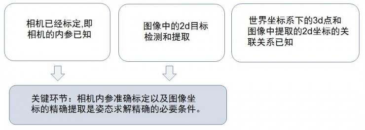
The solution process is as follows:
In the settlement process, the key technical links and problems encountered include: environmental noise point removal, spot center pixel extraction, 2D and 3D point matching, 6DoF calculation iterative optimization, and multi-sensor fusion problems.
境
2. Environmental noise point removal problem environmental environment
In the field of computer vision and image processing, one of the most common problems, and often a very troublesome problem, is environmental noise. All image processing problems will face: whether the light is sufficient, the interference and influence of the infrared components and visible light components of various lamps such as sunlight, fluorescent lamps, incandescent lamps, and halogen lamps (which are often present at exhibitions). The means to solve environmental noise include: 1) Use active light sources, which can effectively reduce the impact of day and night, and generally use infrared light sources when using active light sources; 2) Use filters, especially narrow-band filters . When using active light sources, filters are often used to remove unwanted optical components. The most common one, such as the first-generation Kinect, emits infrared light with a wavelength of 828nm. Therefore, it uses 828±15nm. Narrowband filter. This is the most cost-effective method of anti-interference means. 3) Use actively modulated light sources. If the first two measures cannot effectively suppress interference (the most common situation is that it is used outdoors or indoors, but there is sunlight entering), it may be necessary to use an active light source with modulation information. After the CMOS Sensor receives the light signal , the algorithm can filter out light signals without modulation information such as sunlight. Although the use of modulated light sources can further suppress interference, it often has side effects, such as increasing the workload of the processor and reducing the frame rate.
3. The problem of the extraction accuracy of the center pixel of the spot
In the positioning using computer vision, one of the most important factors affecting the positioning accuracy is the extraction accuracy of the spot center. In practical applications, even if the influence of external light is not considered, only the CMOS Sensor itself will bring various noises to the spot imaging, including: readout noise, dark current noise, fixed pattern noise, etc. Ideally, the optical system can project the parallel beam of the light spot onto one or several pixels of the CMOS sensor, so that the distribution of the light is uniform in one or a few pixels in the center, while the rest of the pixels have no light. But in fact, due to the imaging error, diffraction, and noise of the CMOS sensor in the optical system, the imaging results often show a normal distribution of light intensity centered on a certain pixel. In order to improve the pixel extraction accuracy of the spot center, the hardware approach is to achieve higher-precision image extraction by increasing the resolution of the camera, but this will also increase the hardware cost accordingly. Moreover, with the increase of resolution, the amount of operations also increases geometrically, which will also bring the performance increase of the processor, which will greatly increase the overall cost. In addition, at the algorithm level, some traditional grayscale centroid extraction algorithms are used. The general practice is to solve the centroid of the light spot by preprocessing the image binarization and then using the connected domain extraction. When the brightness is relatively uniform, the accuracy of the centroid extracted by the traditional method is better. However, in actual situations, the brightness distribution of the light spot is often not very uniform, especially in the case of a long distance, the uniformity and size of the brightness will decay rapidly. , which greatly reduces the accuracy of the centroid. The improved method includes first densely upsampling the connected domain range and then weighting the pixel brightness in the upsampling range to solve the centroid. This method can achieve higher sub-sub-pixel accuracy in effect, but sacrifices more operations. efficiency. But if we make some improvements to the algorithm, it is possible to improve the extraction accuracy to sub-sub-pixel level. Huanchuang Technology has carried out in-depth research on this point, starting from the point of view of spot imaging, analyzing the attenuation process of spot brightness, thus summarizing a preprocessing method, so that the centroid extraction accuracy is maintained at sub-sub-pixel accuracy. , without sacrificing any operational efficiency.
4. Two-dimensional and point matching problems
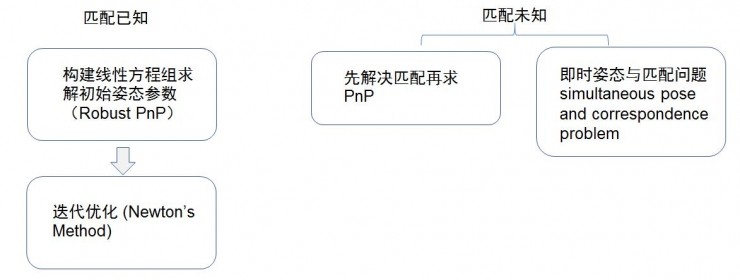
For the single-purpose attitude solution, the PnP principle is the basis of the solution. However, the premise of the PnP solution is that the correspondence between the 3D coordinates in the space and the 2D pixels projected by the camera is known. When the matching is unknown, solving the PnP problem becomes more difficult. Complex, in the field of computer vision, this problem is also called Simultaneous Pose and Correspondence Problem (Simultaneous Pose and Correspondence Problem), the more common algorithms for this problem are softPOSIT, BlindPnP, etc. These methods all use the idea of iterative solution to solve the problem. Solving and matching comes down to an optimization problem, alternately solving the current optimal posture and optimal matching. Compared with softPOSIT, BlindPnP adds some prior posture information, and applies the Gaussian mixture model to 3D-2D matching, which can be achieved in some cases. However, the common problem of these methods is that they cannot ensure that the results are globally optimal. Due to the complexity of the solution space, there is a possibility of not converging or converging to a local optimum, resulting in the failure of the solution. Therefore, some ideological frameworks based on Branch-and-Bound and Bundle Adjustment global solution have been gradually applied to this problem, and good results have been obtained. In general, 3D-2D matching and attitude solving are inseparable. The robustness and efficiency of the matching algorithm directly determine the performance of attitude solving, and it is also a crucial link in all vision-based spatial positioning systems.
5. The problem of fusion with the IMU sensor in the case of camera motion
As early as the era when inertial measurement units (IMUs) were not yet widely popularized, SLAM systems often only relied on image information captured by cameras for spatial positioning. Since the corners or marker points in the image information can directly constrain the attitude and position of the camera , so pure visual input can ensure that there is no drift in the tracking results of the SLAM system in a small space. However, the limitation of pure visual positioning is that its frame rate is often not very high, and the image operation is complicated, so that the pose solution does not have high dynamic performance. In turn, the inertial measurement unit has excellent instantaneous dynamics, which can make up for the shortcomings of the visual system. Therefore, the Vision-Inertial Navigation System (VINS), a spatial positioning system that integrates vision and inertial units, has become the best solution for the current popular SLAM system. In the field of VR, this is also the basis of the inside-out positioning system. The core of VINS is to use the Kalman filter to pre-integrate the input of the inertial unit, and use the integration results to predict the projected positions of all corners or marker points in the camera under the current attitude, and then use the corners or markers captured by the camera. The point coordinates are used to correct and update the predicted pose, and the entire prediction and update process are alternately performed. The current popular IMU output frame rate can reach 1000 frames, so VINS can predict the current attitude at a high frame rate, and at the same time update and correct the attitude at a relatively low image frequency, which can ensure the instantaneous positioning system at the same time. Responsiveness and long-term accuracy.
The above are some technical introductions of monocular spatial positioning. In the follow-up, this column will also introduce some technologies related to spatial positioning and measurement in combination with some practical applications and products.